Overview
The FlipMods Elite V2 by Sacred Labs is an 18-pin board that connects to the GPIO on top of the Flipper Zero device. It features an ESP32-C5 chip with Marauder firmware pre-loaded, a CC1101 for Sub-GHz operations, an NRF24 for 2.4GHz device testing, and a GPS module that can send data to either the ESP32 or Flipper Zero.
Key Features
- ESP32-C5: Marauder firmware pre-loaded, dual-band 2.4GHz & 5GHz WiFi
- NRF24: 2.4GHz wireless device testing
- CC1101: Sub-GHz frequency extension
- GPS Module: Location data for Marauder or Flipper Zero
- USB-C Port: Easy firmware updates
- Micro SD Slot: Expandable storage for Marauder
- 18-pin GPIO: Secure, flat connection
Important Requirements
You will need unofficial firmware on your Flipper Zero. We use and test devices using Momentum firmware, but you may choose another one that supports the required applications.
View Firmware GuideBoard Components
For a comprehensive guide covering all components and their functionality, visit our detailed components guide:
Component GuideESP32-C5 with Marauder
Chip: ESP32-C5
Primary Use: WiFi security testing and Bluetooth scanning
What is Marauder?
ESP32 Marauder by justcallmekoko is a comprehensive WiFi and Bluetooth testing suite that comes pre-loaded on FlipMods boards. It provides capabilities for:
- WiFi network scanning and analysis
- Deauthentication attacks on WiFi networks
- Bluetooth device scanning
- And many more which you could find in the wiki
Dual-Band WiFi
The ESP32-C5 supports both 2.4GHz and 5GHz WiFi bands, meaning Marauder operations can be performed on both bands.
How to Access Marauder
Navigate to: Apps > GPIO > ESP > [ESP32] WiFi Marauder
To learn more about how Marauder works and explore advanced features, visit the official documentation:
Marauder WikiUpdating Marauder Firmware
Keep your ESP32 Marauder firmware up to date for the latest features and security improvements. Use the Web Flasher for easy browser-based updates.
View Update Guide Web FlasherHardware Controls
USB-C Port: Used for uploading firmware to the ESP32-C5 chip.
R/Reset Button: Resets the ESP32 chip. Use if the ESP32 becomes unresponsive or after firmware updates.
B/Boot Button: Puts ESP32 into boot/flash mode. Hold while connecting USB for firmware updates or troubleshooting.
NRF24 Module
Frequency: 2.4GHz
Primary Use: Wireless mouse/keyboard testing
What is NRF24?
The NRF24 module operates on the 2.4GHz frequency band and is designed to test the security of wireless mice and keyboards that use unencrypted communications.
Using NRF24
Set your board's switch to the NRF24 position. Use the [NRF24] Sniffer application to scan for vulnerable wireless mice and keyboards, then use [NRF24] Mouse Jacker to test connections.
Important Limitations
- Only works with vulnerable devices
- Not every wireless mouse/keyboard will work
- Device must use insecure communication protocols
- Modern devices with proper encryption won't be affected
CC1101 Module
Optimal Frequency: 433MHz
Primary Use: Sub-GHz range extension
What is CC1101?
The CC1101 is a sub-GHz transceiver that significantly extends the range and capabilities of your Flipper Zero's built-in Sub-GHz radio. It's designed for the 433MHz frequency band.
Key Benefits
- Extended Range: Much greater transmission/reception distance
- 433MHz Focus: Excellent performance on the most common frequency
Using CC1101
Set your board's switch to the CC1101 position. Open SubGHz application → Radio Settings → Change module from "Internal" to "External". The CC1101 module now enhances all SubGHz applications with extended range and better signal quality.
Important Limitations
CC1101 chips perform best on 433MHz due to the enhanced chip and antenna configuration. While other frequencies work, 433MHz provides the best range and signal quality.
GPS Module
Antenna: Brown cube antenna
Primary Use: Location data for Marauder or Flipper Zero
What is the GPS Module?
The GPS module provides location data that can be sent to either the ESP32 for use with Marauder applications or to the Flipper Zero for location-based features.
Using GPS
Use the GPS switch on the board to select where GPS data is sent — either to the ESP32 or to the Flipper Zero based on your needs.
To enable GPS functionality with Momentum firmware, open the "MNTM" app → "Protocols" → "GPIO Pins" → "NMEA GPS UART" and select "Extra 15,16".
GPS Signal Acquisition
For best GPS performance, use the device outside in an area with clear sky view and no obstructions that could block the brown cube antenna.
Antennas
The Elite V2 requires three antennas for optimal performance. Look for frequency labels printed next to each antenna connector on the board.
Dual-Band 2.4/5GHz Antennas (2 Required)
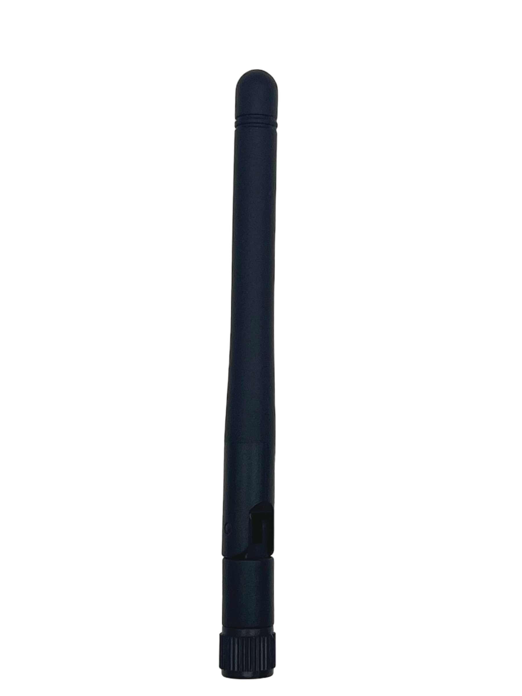
Used for: ESP32-C5 and NRF24
433MHz Antenna (1 Required)
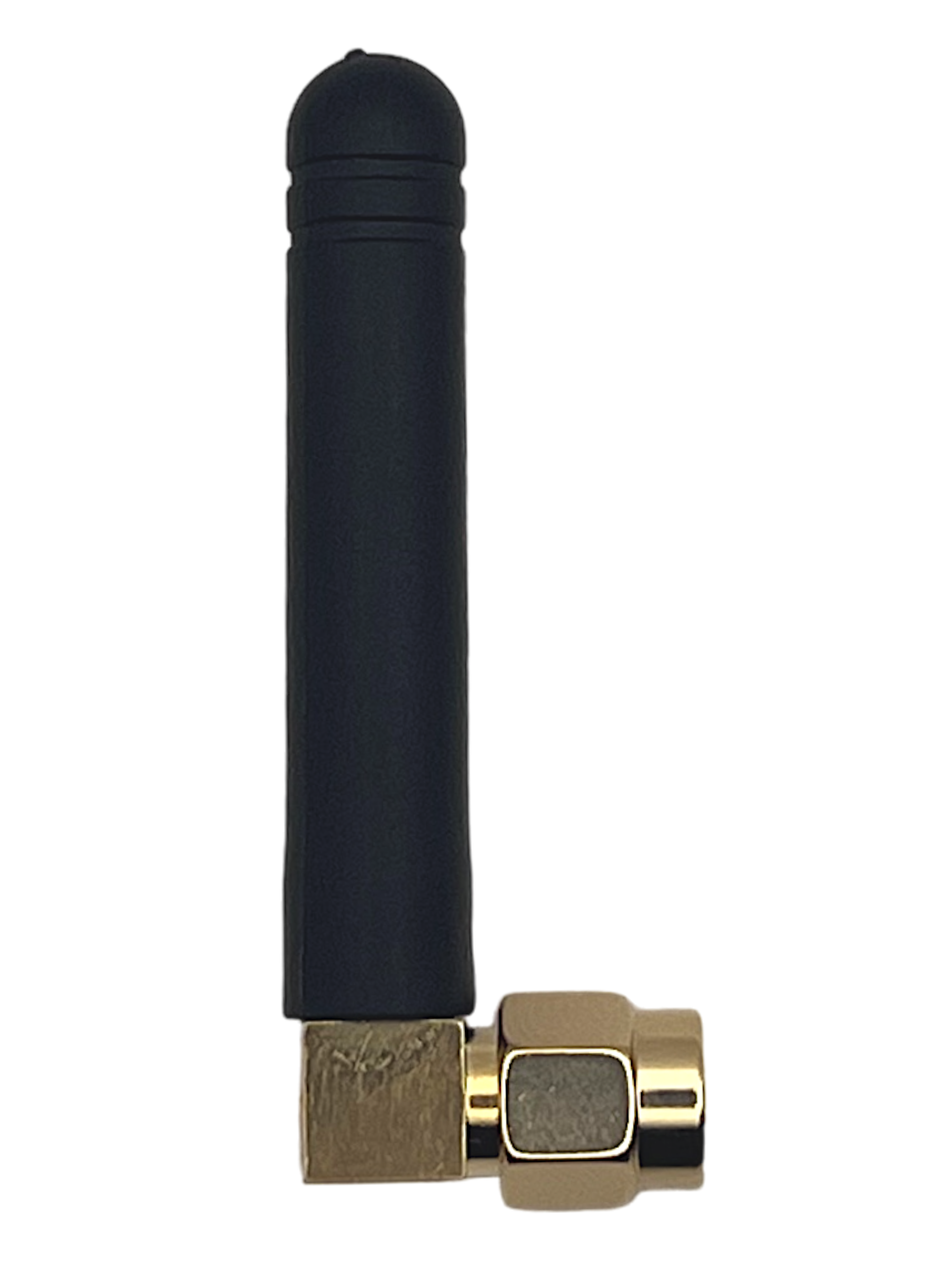
Used for: CC1101
Hardware Controls
NRF24 / CC1101 Switch
Toggle between NRF24 and CC1101 modules. The ESP32-C5 with Marauder remains powered regardless of switch position.
GPS Switch
Toggle between sending GPS data to ESP32 or Flipper Zero. Set before powering on the device.
Setup Instructions
Install Unofficial Firmware
Flash your Flipper Zero with Momentum firmware for full compatibility.
View GuidePrepare SD Card (Optional)
Use an SD card ≤32GB, initialized as FAT32. Some brands may not work with Marauder — ensure the SD card is inserted before turning the board on.
Set Switch Positions
Set the NRF24/CC1101 switch to your desired module and the GPS switch to your preferred destination (ESP32 or Flipper Zero) before turning on.
Connect Board Safely
Ensure the Flipper Zero is off when plugging the Elite V2 in.
Video Tutorial
Legal Notice
Always ensure you are following the laws and regulations of your area when using all components. Only test on networks and devices you own or have explicit permission to test. The user is fully responsible for complying with all applicable laws and regulations.